Modern Central Heating
6 Microbore & Underfloor Systems
 |
Microbore systems were very popular in the 1970s. The pipework for these
early systems was copper. In modern construction microbore is once again
becoming popular - but this time using plastic pipes. The pipework which circulates the water to the radiators is
divided into two sections:
A pump is used to force the water around the system, although it will usually have to be slightly more powerful than with an ordinary small-bore system because of the smaller pipe diameter. There are a number of advantages to microbore systems:
|
 |
 |
There may, however, be a greater risk of blockage and copper microbore pipes
are easily crushed.
In hard water areas, lime scale can build-up in the pipework so
additives or a water softener are essential.
The pipework between the manifolds and each radiator is normally kept below 5 metres, and, in early installations, special radiator fitting were used so that both the feed and return micro bore pipes are connected to the same end of each radiator. The graphics either side show the Hep20 manifold system. The pipes which run from the manifold to the radiators are 10mm, the feed and return from the boiler 22mm. |
 |
 |
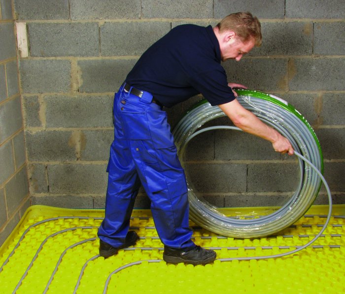
The development of plastics in coils has led to a resurgence in underfloor heating systems. These were common (but not very popular) during the 1960s when they tended to be electric wires embedded in solid floors (left) or water pipes hidden in suspended ceilings (right). They were moistly found in high and medium-rise housing. They were unpopular because they were unreliable, expensive to run (especially after fuel prices increased rapidly in the early 1970s) and difficult to control. |  |
Modern underfloor systems |
Modern underfloor systems are much easier to control than their earlier counterpart. They are also far more reliable and efficient. The principle is not so very different from microbore - but instead of the manifold feeding a radiator, it feeds a coil of pipework below the floor. Warm water is circulated through a series of pipes laid in the floor of the room. These pipes form a continuous loop and act to create a large radiant surface that will heat the room to a comfortable temperature. |
This is just a brief introduction Visit the Hep20 web site for more information. |
 |
Underfloor heating leaves wall space free from obstructions, giving more freedom in room layout. It creates a comfortable environment whilst needing lower energy input than traditional radiator systems. Hepworth claim that the heat gradient creates a warm feet, cool head environment in which heat is concentrated at living level rather than being wasted warming the ceiling space. As a consequence energy costs are significantly reduced typically as much as 20%. No radiators also removes the risk of the young and very old being burnt by hot surfaces. |  |
 |
Underfloor heating systems typically have outputs of 80 100 watts per m2. Condensing type boilers are particularly suited to underfloor heating because the low return temperature means that the boiler will frequently operate in condensing mode when the system is running. The underfloor heating system should be connected to the boiler through the manifold. The manifold controls the heat requirement for the underfloor system by blending hot water from the boiler with cooler returned water from the floor circuits. Most boilers have a high output temperature (80 to 85°) to cater for the other heat requirements of the dwelling (e.g. hot water cylinder, radiators and towel rails), which means that they should not be connected directly to the underfloor system. |
Click here for a more detailed pdf showing floor coils and floor sections. layout |
 |
Careful consideration needs to be given to the positioning of the insulation in a ground floor slab (left). Insulation is generally placed underneath the floor slab in order to meet Building Regulations. However, in the case of an underfloor heating system the insulation should be placed above the slab so the heat is conducted up through the floor screed into the room. Pipes can then be fixed directly to the insulation. The thickness of insulation above the slab will vary according to the Building Regulations, but is generally between 50 and 100 mm. Edge insulation should also be positioned around the perimeter of rooms (above the slab), so significantly reducing heat loss through the walls. Pipes are then fixed into position following the appropriate circuit layout. There are various fixing options. Some underfloor heating insulants have pre-formed plastic facings into which the pipe can be located. Alternatively special clips which push into the insulant and hold the pipe firmly can be used. These clips are typically 45mm deep so, to be effective, the insulant depth will need to be greater than this. If there is reinforcing mesh in the screed the pipe can be cable tied to the mesh. In timber floors (right) insulation is battened between the joists and it is also common practice to lay diffuser plates across the insulation to aid an even distribution of heat. | 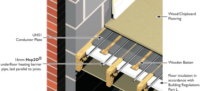 |
except where acknowledged